LuxLibre
LuxLibre › Lights › FlashKa Keychain v0.5
FlashKa Keychain v0.5
On this page: Specifications · Firmware · Building one · Cost · Known limitations · What has been checked · What is in this folder · Licences
LuxLibre reference design #1: a 94.4 × 20 × 16 mm aluminium keychain light with a white LED from 3 mA moonlight to a 2.2 A turbo burst, a Class 2 green laser behind a hardware safety switch, USB-C charging, two small LiPo cells (about 800 mAh) and Bluetooth: a web page on a phone or computer shows the battery and switches the light. Firmware is installed from a web page through the light’s own USB-C port.
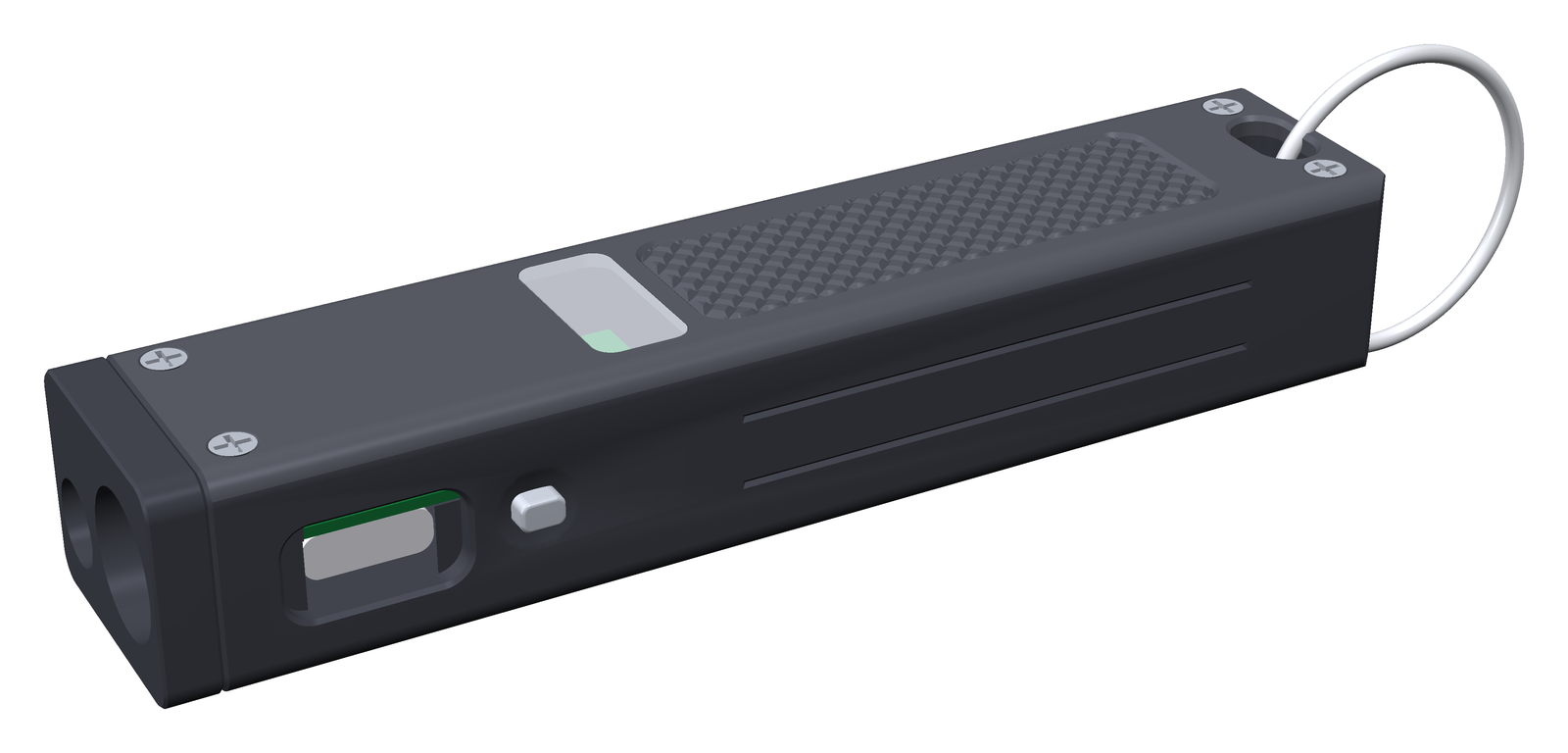
Status: designed, not yet built. Everything here has been checked by software (see checks), but nobody has assembled a FlashKa yet. The first build must go through the bring-up in docs/testing.md and the bench plan in docs/firmware.md section 7 before more are made.
About the file names. The design was developed under the working name “Aurora++”, and the
design files still carry it (Aurora_*.step, kicad/Aurora_main/, the Rust crates
aurora-core and aurora-fw). “Aurora” is also a product line of the flashlight maker
RovyVon, which is one reason for the new name. The files will be renamed in v0.6; until then
“Aurora” in this folder means FlashKa v0.5. The laser-marking artwork already says FLASHKA.
Specifications
| Size and mass | 94.4 × 20 × 16 mm; aluminium tray + lid 29.5 g, about 50 g with cells |
| LED | Luminus SST-20 (5000-6500 K) on a 10 mm copper DTP board |
| LED driver | TLV62585 buck with a current loop (TLV333 op-amp, 20 mΩ sense resistor), 3 mA to 2.2 A |
| Laser | 520 nm module, Class 2 (≤ 1 mW), slide-switch interlock S2 in its supply |
| Cells | 2 × LP601646 LiPo pouch cells in parallel (6.0 × 16 × 46 mm, about 400 mAh each), with protection boards, rated at least 2C continuous (0.8 A each) |
| Charging | USB-C (two 5.1 kΩ CC resistors), TP4057 linear charger, about 300 mA, status on the RGB LED |
| Brain | ESP32-C3-MINI-1 module (Bluetooth LE, USB serial/JTAG) |
| Temperature | NTC 100 kΩ, B 4250, next to the LED driver |
| Circuit board | 24 × 16.5 mm, 4 copper layers, 0.8 mm, ENIG; assembled by JLCPCB (parts on both sides) |
| Housing | CNC-machined 6061-T6, bead-blasted and black anodised (JLCCNC); four small translucent resin parts as one print kit (JLC3DP) |
| Output | not measured yet. Simulated with the LuxLibre FlashKa board header (make sim BOARD=flashka-keychain-v05): default turbo about 445 lm (1.2 A), at most about 510 lm at the cell-current limit, about 250 lm sustained at the thermal limit in 25 °C still air (simulator) |
Firmware: two options
- The v0.5 firmware in firmware/ (Rust, ESP-IDF): Bluetooth app with profiles
(Extreme, Balanced, Endurance, custom), deep sleep, the button always has priority over the
app.
firmware/dist/aurora-fw-v0.5.0-merged.binis the image that the web installer app/aurora-flasher.html writes; the app is app/aurora-app.html. Details: docs/firmware.md, docs/ble_protocol.md, docs/web_apps.md. This is the reference firmware for the FlashKa until the LuxLibre port has been tested. - LuxLibre with the board header firmware/boards/flashka-keychain-v05/board.h and the ESP32-C3 port: the common LuxLibre user interface, console and parameters, but experimental, without Bluetooth and with light sleep instead of deep sleep (see known limitations).
Building one
- Read Aurora_v0.5_Build_Guide.pdf from start to end once (written for people without electronics experience; source: docs/build_guide_v0.5.md).
- Upload the files in order_files/, one folder per shop:
1_JLCPCB(circuit boards with all small parts mounted),2_JLCCNC(aluminium tray and lid, each STEP file with its drawing PDF of the same name, laser marking),3_JLC3DP(the resin print kit). TheREADME.txtin that folder lists the order options. - Buy the remaining parts from the workbook Aurora_Parts_List_v0.5.xlsx (every part with price, link and fee; notes in docs/bom_notes.md).
- Install the firmware with app/aurora-flasher.html (Chrome or Edge on a computer).
Cost
Prices checked on 2026-10-14, delivered to Lithuania (EU, 21 % VAT), from docs/bom_notes.md:
| 1 light | 5 lights (total) | |
|---|---|---|
| PCB + assembly (JLCPCB) | $169.31 | $196.67 |
| Housing (aluminium + resin print kit) | $65.96 | $225.40 |
| Bought parts (cells, LED board, laser, glass, screws, ring) | $56.75 | $211.30 |
| Consumables (wire, tapes, epoxy) | $18.29 | $18.29 |
| Shipping, VAT, customs duty, fees | $219.32 | $329.89 |
| Total | $529.63 (€473.39) | $981.55 (€877.33), $196.31 per light |
| Tools, once | $128.00 |
Where the money goes for one light: shipping, VAT, duty and fees are 41 % (three JLC parcels and eight marketplace parcels, each with its own shipping and customs fee). JLCPCB’s assembly fees are $127.15: set-up for two board sides $51.12, 33 loading fees for non-basic parts $50.49, stencils $16.42, X-ray inspection $6.56. The electronic parts for the two boards JLCPCB assembles at minimum cost only $17.16.
How to make it cheaper
| Change | Saves (1 light, about) | Trade-off |
|---|---|---|
| Economy shipping everywhere | $55 | slower delivery |
| Fewer parcels (one marketplace order, one EU shop) | $30 | fewer shop choices |
| 3D-printed housing instead of aluminium | $70 | much lower sustained output (MEC-1) |
| No laser | $28 | no laser |
| Build five at once | $333 per light | five lights to build |
| Solder the board yourself (parts from LCSC, stencil, cheaper PCB order) | $100-120 | needs the tools and skills below |
Soldering the board yourself is possible but hard: 38 parts in 0402 (1.0 × 0.5 mm), a 1.0 × 1.0 mm RGB LED without leads, ESD diodes in SOD-523 (1.2 × 0.8 mm), the TLV62585 in SOT-563 (1.6 × 1.2 mm, 0.5 mm pitch), a USB-C receptacle with 0.5 mm pitch, and the ESP32-C3 module and LED with pads underneath, on both sides of a 24 × 16.5 mm board. That needs solder paste, a stencil, a hot plate or hot-air station, a microscope or strong magnifier, and practice (roughly $60-150 of tools).
v0.6 ideas that attack the fees instead of the parts: all parts on one side (DFM-1), fewer unique part numbers and more basic parts (DFM-2), 0603 instead of 0402 and a larger RGB LED (no X-ray, easier hand soldering, DFM-3), possibly a slightly larger board.
Known limitations
| Topic | Limitation | Rule | Plan |
|---|---|---|---|
| Verification | not built and measured yet | FW-8, THM-6 | first build with the full test plan |
| Cells | pouch cells soldered in; the EU requires user-replaceable portable batteries from 18 February 2027 | BAT-2 | v0.6: cells on a connector, screws only, no glue |
| Standby | the v0.5 firmware expects about 29 µA in deep sleep (10 µA + 17 µA for the NTC divider + 2 µA for the battery divider), close to the 33 µA budget; the LuxLibre port’s light sleep is higher | BAT-6 | switch the NTC divider from a GPIO; deep sleep in the LuxLibre port |
| Cell current | the 2.2 A “Extreme” profile of the v0.5 firmware draws about 2 A from two 2C cells (1.6 A rating); the LuxLibre header limits the cell current to 1120 mA (70 % of 2C) | BAT-1 | use 3C cells for the Extreme profile (and BAT_MAX_MA 1680) |
| Capacitor derating | C5, the 22 µF 6.3 V X5R 0603 input capacitor of the buck on VBAT (up to 4.2 V), is rated below twice its working voltage | DRV-4 | v0.6: 10 V or more, checked against the DC-bias curve |
| USB detection | the board has no VBUS sense pin; the firmware has to enable the charger briefly to see USB (the LuxLibre port does this only inside the charge temperature window) | CHG-3 | v0.6: a VBUS divider to a GPIO |
| Bluetooth | only in the v0.5 Rust firmware, not in LuxLibre yet | LuxLibre Bluetooth service | |
| Assembly cost | parts on both sides, 33 non-basic parts, leadless parts needing X-ray | DFM-1 to DFM-3 | v0.6 layout |
| Names | design files still named “Aurora” | rename in v0.6 | |
| Indicator | the red LED shares the ESP32-C3 UART TX pin and flickers during the ROM boot messages | move the red LED to another pin in v0.6 |
What has been checked
From the v0.5 build scripts: schematic netlist equals the intended netlist (39 nets); the PCB is routed completely with 0 KiCad DRC errors against JLCPCB’s 4-layer rules (silkscreen warnings only); every ground pad is tied to the inner ground plane; courtyards, keep-outs and the housing interface (cad/housing_interface.json); housing walls, PCB insertion path, button travel and the real PCB inside the housing (0 collisions); firmware logic (93 unit tests); app and installer against a simulated light (123 tests); cost workbook (803 formulas, recalculated independently). None of this replaces a built and measured light.
What is in this folder
| Folder / file | Contents |
|---|---|
| Aurora_v0.5_Build_Guide.pdf | ordering, firmware, assembly, first use, troubleshooting; appendix: user manual |
| Aurora_v0.5_Hardware_Package.pdf | why and how v0.5 was designed (design-log chapter; source docs/ch12_v0.5_bluetooth_redesign.md) |
| order_files/ | exactly the files to upload at JLCPCB, JLCCNC and JLC3DP |
| production/ | Gerbers and drill (zip), BOM and CPL for JLCPCB assembly, schematic PDF, DRC report, assembly drawings, layer pictures, netlist |
| kicad/ | KiCad project (schematic and routed 4-layer PCB, design rules) and the project footprints |
| cad/ | housing STEP and STL files, JLCCNC drawings (DXF, PDF, PNG), laser-marking DXF for the Class 2 laser (a Class 3R variant from the original design is kept for reference only: LuxLibre’s LAS-1 allows Class 1 and 2 lasers only), print kit, reference assembly STEP, PCB STEP, housing_interface.json (the contract between housing and PCB) |
| firmware/ | the v0.5 Rust firmware source and the built image in dist/ |
| app/ | the Bluetooth web app, the firmware installer and a start page (single HTML files that work offline), screenshots |
| renders/ | pictures of the light, the exploded view, the print kit, a size comparison |
| docs/ | Markdown sources: build guide, design chapter, firmware, Bluetooth protocol, web apps, cost notes, housing notes |
| tools/ | the generators: kicad/ (schematic, placement, router, production files), housing/ (CAD, drawings, renders, fit checks), web/ (installer build and tests), parts_list.py (cost workbook) |
| assets/ | figures used by the design chapter |
Rebuilding after a change
python3 tools/housing/aurora_housing.py cad          # housing STEP/STL + housing_interface.json (~15 min)
python3 tools/kicad/build_all.py                     # schematic, placement, routing, DRC, JLC files (~10 min)
python3 tools/housing/drawings.py cad cad            # JLCCNC drawings and laser-marking artwork
cd firmware && ./build.sh                            # Rust firmware + merged image
cd tools/web && npm install && node build_flasher.mjs   # installer page with the new image
python3 tools/parts_list.py                          # cost workbook (checks itself)
python3 docs/build_pdf.py                            # the two PDFs
The generators need Python 3 with CadQuery (OCP), ezdxf and KiCad 7 or newer (for kicad-cli);
the firmware needs the Rust ESP toolchain (see docs/firmware.md).
Licences
Hardware design files (KiCad, CAD, drawings and their PDFs, production files): CERN-OHL-W-2.0. The v0.5 Rust firmware, the web app and the web tools: MIT OR Apache-2.0. The Python generator scripts: GPL-3.0-or-later. The build guide, design chapter and other documents: CC-BY-SA-4.0. Details and what they mean for building and selling FlashKa lights: LICENSING.md.